Compressor Drive - Offshore Production Platform
In this case history the current spectrum of one compressor motor is compared to another which exhibited excessive vibrations.
3-phase, SCIM, 134 kW/180 h.p.
440 V, 210 A, 1485 r.p.m., 50 Hz, 0.88 p.f.
star connected.
Aluminium die cast rotor,
single cage design
58 rotor slots.
Full-Load Slip = 0.01 or 1%
analysis of faulty Motor B
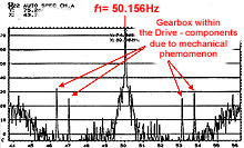
Figure b-3
Motor A spectrum - Healthy
analysis of faulty Motor B
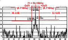
Figure b-4
Motor B spectrum - Unhealthy
MCSA FFT Current Spectrum
Dynamic Range = 80 dB
Frequency Resolution = 15.6 milliHertz/line
The normal duty cycle of the motors was 15 minutes ON and 15 OFF and they were started "direct-on-line (D.O.L)".
During the MCSA tests Motor "A" was operating normally. and the problem Motor "B" was on for 10 minutes and off for 1 hour.
General
Symptoms
Prior to MCSA being applied the client reported that Motor (B) was producing
pulsating vibrations and an audible beating noise. Motor (A) was operating
normally.
Vibration analysis of Motor (B) by the operator suggested that the motor
bearings were possibly faulty. The motor was removed from the installation
and new bearings were installed but the motor was only tested on no-load.
The client was told the motor was now healthy but if it were a broken
rotor bar problem it would not be detectable on no-load since the rotor
current is small and the fault characteristics would have been negligible.
The motor was reinstalled with the new bearings but exactly the same pulsating
vibration and audible noise were present.
There was considerable debate between the mechanical and electrical maintenance
staff concerning the real problem. For example, was it broken rotor bars,
abnormal airgap eccentricity, or a compressor/gearbox problem?
EXPERT
COMMENT
The
current spectrum in Figure b-3 shows a healthy rotor winding
- This current
spectrum shows there are no ±2sf
1sidebands
- Note
that the supply frequency was 50.156 Hz and not 50 Hz (isolated offshore
power system). Cannot use the nameplate frequency to predict the ±2sf1
sidebands - the actual f1
from the measured current spectrum must be used.
- Due to
the gearbox in the drive there are current components due to the mechanical
drive characteristics - different shaft speeds, etc.
- The motor
was operating at 120 A, ie 57% of the full-load nameplate current of
210 A.
Note this does not mean the motor was delivering 57% of the rated full-load nameplate output power.
- The full-load
rated slip (deduced from the full-load nameplate rotor speed and supply
frequency) sf.l.=
0.01 or 1%.
- On this
reduced load the slip will be less than 1%.
- If ±2sf
1sidebands were present due to broken rotor bars then they would be less than ±1 Hz around f1- no sidebands exist.
 |